CS775 Open Project
Depixelizing Pixel Art
Jai Mashalkar ( 113050007 ), Ahana Pradhan ( 113050039 )


EPX SuperEagle Hq4x Our algorithm
Background
In this project, our aim is to upscale very low resolution pixel art images to any desired level while preserving the very small features. This is accomplished by first identifying all the features in the image, reshaping the pixels accordingly and then fitting splines along the boundary of every feature so that the output image becomes quite smooth at any desired resolution. In order to get a smooth gradation of colors in the final image, color diffusion is done.
User Instruction
- Command for compilation :
make
- Command for execution:
./depixel < image-name >
- Key instructions:
- 0 : Grid with boundaries of reshaped pixels
- 1 : Only visible edges of reshaped pixels
- 2 : Splines, reshaped pixeled image with color ( without diffusion )
- t : toggle between showing control points of spline
- p : Only reshaped pixels
- o : only splines
- 3 : Splines, reshaped pixeled image with color diffusion
- + : Upscale
- - : Downscale
- u : scroll upward
- d : scroll downward
- l : scroll left
- r : scroll right
- c : capture current window to output image ( ppm ) file
Implementation details
The basic data structure used contains lists of points, edges and pixels. Points have indices of edges they are a part of,
edges have indices of their endpoints and cells they belong to. Pixels have color values, edges and some connectivity information.
Details about the individual parts are as mentioned below:
- Similarity Graph
Initially, the image is read and lists for points, edges and pixels are created. Then a similarity graph is made by comparing yuv colors of adjacent pixels.
Unnecessary diagonal connections are detected by checking if a pixel is connected to its right neighbour as well as its right diagonal bottom pixel.
If a diagonal connection necessary, and is conflicting with another diagonal connection (2 diagonals though same node) then the following heuristics are used to
resolve ambiguities:
- Curves: Ratio of lengths of curves is found by following valence two nodes till possible, for each diagonal.
- Connected Components: Ratio of sizes of connected components is found using breadth first search over a region of 8x8 (if it exists), for each diagonal.
- Island Pixel: If any of the four pixls involving the two diagonals has valence 1, it is called as island pixel.
- Isolated Pixel: If a pixel is not connected to any pixel, due to connections of neighbouring pixels, it gets reshaped to a small size.
In order to avoid this artifact, we detect and avoid reshaping of isolated pixels.
The scores returned by these heuristics are added up and compared to find out the more important connection.
We were not able to determine if curves heuristic was better than connected pixels, hence equal weights were given to those two.
However island pixel was more important, hence higher weight was assigned to it.
After important connection is identified, the other connection is removed. After this step, pixels are reshaped.
- Reshaping Pixels
Since the method mentioned in the paper was not generalized. It included finding an exhaustive list of possible shapes of similarity graph around a node,
and assigning a new shape to each of them. It was not possible to find such an exhaustive list. So we have implemented a generalized method to reshape pixels which is as follows:
At every step, if needed, the right bottom corner of a pixel is modified if needed so that related pixels get reshaped.
If there exists a diagonal connection through the concerned point, the point is split into an edge, which joins the cells connected by the diagonal.
For this, a new point is created, and the current point is moved, both at an offset of 0.25 in the concerned directions.
Though this method gives a little different geometry than the method followed in the paper, the accuracy of features seen in final image is not affected.
This process is iterated over all nodes. Thus all points get considered for reshaping and we get reshaped pixels as desired.
- Spline Fitting
- Visible Edge Detection
Once the pixels are reshaped, edge list contains all the edges including the additional edges from the reshaped pixels. Visible edges are identified by comparing the colors of two sides of an edge. Two different color in two sides results a visible edge. Excluding all other edges than visible edges results the outline of the image.
- Control Point Extraction
From the list of visible edges, end points of each visible edges are stored as cotrol points for spline generation. Along with the control points for a spline, color value is also stored. Between the two colors in two sides of first visible edge of a feature, darker one is chosen as the color value for the bounding spline for this feature. There are the number of control point set equal to the number of distinct features. While enumarating control points sequencially, a set of control points is formed by the longest possible chain of control points in a sequence.
- Spline Generation
Here quadratic B-splines are used with open uniform knot vector. Each spline is drawn using corresponding set of control points and with the stored color value.
- Rendering
In the paper, rendering is done by storing control points of splines and colors on either sides. It involves breaking down the spline into lot of small line segments and then placing inclined rectangles of corresponding color on either sides. Thus the whole image is filled with color with colored rectangles. After that, diffusion was done using a filter with a progressive radius.
It was too complicated to follow the above mentioned method. Also, finding out features was not taking too much time. So we decided not to create entirely different programs for feature detection and rendering. We first draw the reshaped pixels obtained from the first stage as polyons using OpenGL.
In order to make edges look smooth, splines are superimposed on the polygons. The color of the splines is taken as the color of the first control point, hence some artifacts are seen. The width of splines is increased on increasing the size of the image.
OpenGL does diffusion by default if the colors of different vertices of a polygon are different. We are already drawing pixels as polygons, so we decided to use this feature for implementing diffusion.
If color of two neighbouring pixels is different, but less than threshold, the average of the two colors is assigned to points belonging to the edge connecting the two pixels. Hence we can see a smooth gradient along the boundary of the two pixels.
There are some cases where this method fails. Since our method consideres each pixel one by one,a point gets drawn multiple times, for whichever pixels it is a part of. If it gets assigned different color in different pixels, then OpenGL does not assign it an average color. So sharp change of color gets seen at such points.
In order to fix this, instead of looping over pixels, we need to loop over points. Each point should be assigned a color based on all the pixels it belongs to. If this is done, we will be able to see smooth diffusion across the image. Due to lack of time we could not implement this method.
- Our Results
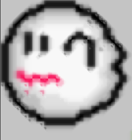
The following is the input image. Original size of this pixel art is 18x18 while it is shown 250x250 here. We see how low resolution pixel art degrades in quality when upscale by usual techniques.

The following sequence shows output from various stages.

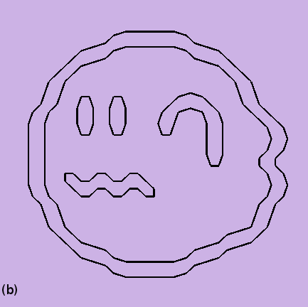
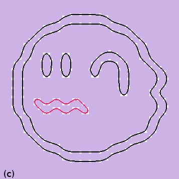
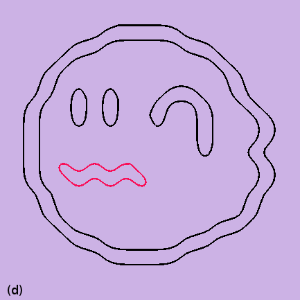
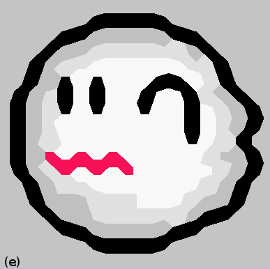
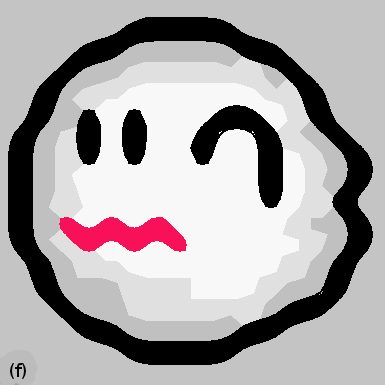
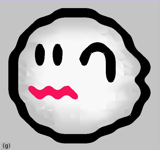
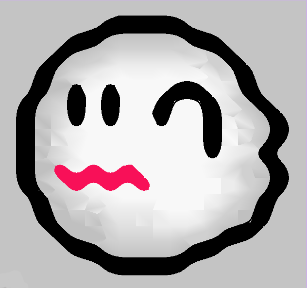
(a) Reshaped pixel grid. (b) Only visible edges. (c) Splines are fitted with color information, control points are shown by white. (d) Only splines. (e) The reshaped pixel grid is filled with original colors. (f) Reshaped pixel grid filled with original color and colored splined are merged alongwith (g) Final result having color diffusion.
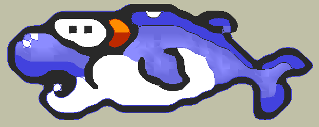
Following are results for some other inputs. Each pair of the following are input-output images.
(a)
 (b)
(b)
 (c)
(c)
 (d)
(d)
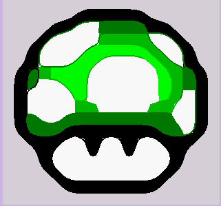
(a) Input image size 42x18, output image size 300x150. (b) Input image size 34x18, output image size 300x150. (c) Input image size 15x15, output image size 250x250. (d) Input image size 18x18, output image size 250x250.
References
[1] Depixelizing pixel art, Kopf, Lischinski, ACM
Transactions on Graphics (SIGGRAPH 2011)
[2] Vectorization of Pixel Art,
Christian
Loos. http://www.multimedia-computing.
de/mediawiki//images/3/37/Diploma\
_Thesis-ChristianLos.pdf
[3] http://research.microsoft.com/en-us/um/people/kopf/pixelart/supplementary/multi_comparison.html