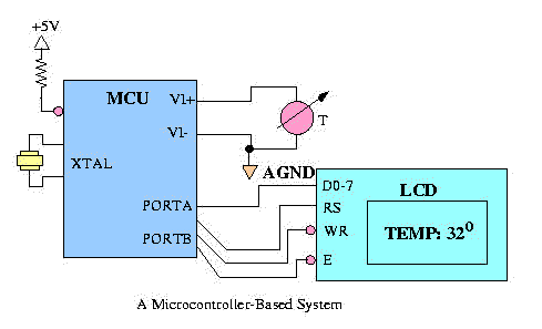
So far we have studied LSI/VLSI chips that provide a CPU, memory, general purpose interfaces. We can build a microcomputer using these chips with the help of additional SSI/MSI components that include latches, drivers, decoders, etc. which is normally termed as Glue logic. This is a microcomputer built using separate components (CPU, Memory, etc.). For some specific applications, we also have single chip computers in a VLSI chip. This single chip microcomputer will have a CPU, memory and I/O interfaces, timers, ADC/DACs etc. on a single chip itself. This component is called a Single Chip Microcontroller. Nowadays it is also being referred to as an Embedded System or to some extent it could also be called at System-on-Chip (SoC). The term SoC is generally at the high-end of the single chip microcontroller. This could be used for specific purposes. Since memory and I/O interfaces are available on the chip alongwith the CPU itself, there will be some constraints on the amount of memory and interfaces that could be provided on the chip itself. As we will see later, the currently available microcontrollers will have limited amount of memory in terms of ROM, EPROM, Flash ROM/RAM and I/O ports. If this chip could be used as it is for a specific application it will be highly beneficial and system built around a single chip microcontroller would be highly reliable. One can go to a ROM based microcontrollers if the production volume is large. For prototyping and limited applications, one can go for EPROM or Flash ROM based single chip microcontrollers.
The manufacturers of Single chip microcontrollers will provide facility to have external memory, if required but one may have to sacrifice some I/O ports to have this extra memory requirement. Now we will study the Single chip microcontrollers in details.
Table : Examples of Typical microcomputer applications
| Consumer | Function Performed by the Microcomputer |
| Washing Machine | Controls the water and spin cycles |
| Exercise equipment | Measures speed, distance, calories, heart rate, logs workouts |
| Remote controls | Accepts key touches and sends infrared (IR) pulses to base system |
| Clocks and watches | Maintains the time, alarm, and display |
| Games and toys | Entertains the user, joystick input, video output |
| Audio/video | Interacts with the operator and enhances performance |
| Communication | |
| Telephone answering machines | Plays outgoing message, saves and organizes messages |
| Telephone system | Interactive switching and information retrieval |
| Cellular phones and pagers | Key pad inputs, sound I/O, and communicates with central station |
| ATM machines | Provides both security and banking convenience |
| Automative | |
| Automatic banking | Optimizes stopping on slippery surfaces |
| Noise cancellation | Improves sound quality by removing background noise |
| Theft deterrent devices | Keyless entry, alarm systems |
| Electronics ignition | Controls sparks and fuel injectors |
| Power windows and seats | Remembers preferred settings for each driver |
| Instrumentation | Collects and provides the driver with necessary information |
| Military | |
| Smart weapons | Recognizes friendly targets |
| Missle guidance systems | Sense car positions and controls traffic lights |
| Global positioning systems | Determines where you are on the planet |
| Industrial | |
| Setback thermostats | Adjusts day/night thresholds, thus saving energy |
| Traffic control systems | Senses car positions and controls traffic lights |
| Robot systems | Input from sensors, controls the motors |
| Bar code readers and writers | Input from readers, output to writers for inventory control and shipping |
| Automatic sprinklers | Used in farming to control the wetness of the soil. |
| Medical | |
| Apnea monitors | Detects breathing and alarms if the baby stops breathing |
| Cardiac monitors | Measures heart functions |
| Renal monitors | Measures kidney functions |
| Drug delivery | Administers proper doses |
| Cancer treatments | Controls doses of radiation, drugs, or heat |
| Pacemakers | Helps the heart beat regularly |
| Prosthetic devices | Increases mobility for the handicapped |
| Dialysis machines | Performs functions normally done by the kidney |
These applications require special electronic devices that performs functions which are very dedicated for their purpose. It doesn't require operating system, only application programme which one can write and put in the memory. Nowadays we are having another word called Embedded where the hardware part is a microcontroller or it can be a Application Specific Integrated Circuit (ASIC).
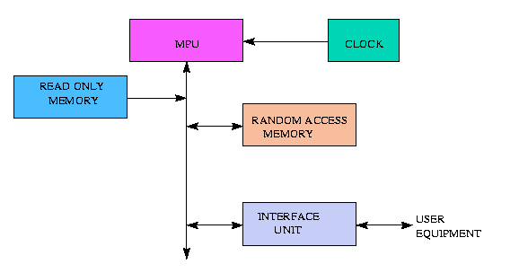
CPU + Interface
CPU + ROM + RAM + Interfaces + Timers + A/D, D/A Converter
For prototyping ROM is replaced by EPROM. ROM is essentially used for programing code.
CPU + EPROM + RAM + Interfaces + Timers + A/D, D/A Converters
CPU + FLASH ROM + RAM + Interfaces + Timers + A/D, D/A Converters
Examples : 8048, 8748, 8051, 8751, i960, 6801, 68701, 68HC11, etc.
On chip ROM, RAM (Code and data memory), interfaces are very limited. (Examples - ROM, EPROM, 4 KB, RAM 256 B)
Reliability + Suitable for specific application without additional external hardware.
Also provision is available to expand memory outside the chip.
For Examples of Motorola and Intel's Microcontroller chips, see table
AT91 MCU Products
|
Device |
Max Speed MHz |
Temp | Flash Bytes |
ROM Bytes |
RAM Bytes |
MPI | PDC | Additional Features |
IEEE 1149.1 |
Package | Supply Volt |
| AT91M40400 | 33 | C/I | - | - | 4k | - | 4-ch | 3 Timers, WD 2 USARTS |
- | TOFP100 | 1.8-3.6 |
| AT91F40416 | 25 | C/I | 2M | - | 4k | - | - | BGA120 | 2.7-3.6 | ||
| AT91M63200 | 25 | C/I | - | - | 2k + 1k | y | 8-ch | 6 Timers, WD SPI, 3 USARTS PMC |
y | TOFP176 | |
| AT91M43300 | 25 | C/I | - | - | 3k | - | y | BGA144 | 1.8-3.6 | ||
| AT91M40100 | 40 | C/I | - | - | 1k | - | 4-ch | 3 Timers, 2 USARTS Watchdog PMC |
- | TOFP100 | 2.7-3.6 |
| AT91M40800 | 40 | C/I | - | - | 8k | - | - | ||||
| AT91R40807 | 33 | C/I | - | - | 8k + 128k | - | - | ||||
| AT91M40403 | 33 | C/I | - | 32K | 4k | - | - | ||||
| AT91M40807 | 33 | C/I | - | 128K | 8k | - | - | ||||
| AT91M55200 | 33 | C/I | - | - | 2k | - | 10-ch | 8-ch ADC 2-ch DAC RTC, Clock Generator APMC, 6 Timers, WD SPI, 3 USARTs |
y | TOFP176 | 2.7-3.6 |
| AT91M55800 | 33 | C/I | - | - | 8k | - | y |
PDC - Peripheral Data Controller
MPI - Multi Processor Interface
WD - Watchdog
PMC - Power Management Controller
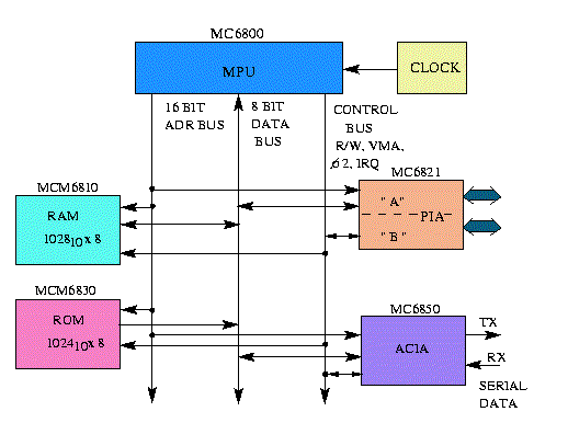
Now we will take a small case study of Motorola's 6801. Following are the essential features of this Microcontroller.
Pin Assignment Diagram
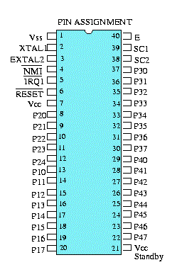
31 - Port lines
1 - Vcc
1 - Ground
1 - Standby
1 - Clock In and Clock Out
2 - Crystals
2 - Interrupts
1 - Reset
2 - External
Internal Organisation of the Chip is given in the Figure below:
MC6801 - Single chip Microcomputer
It is recommended to be used in the Single chip mode and connection for the single chip mode is given in the diagram.
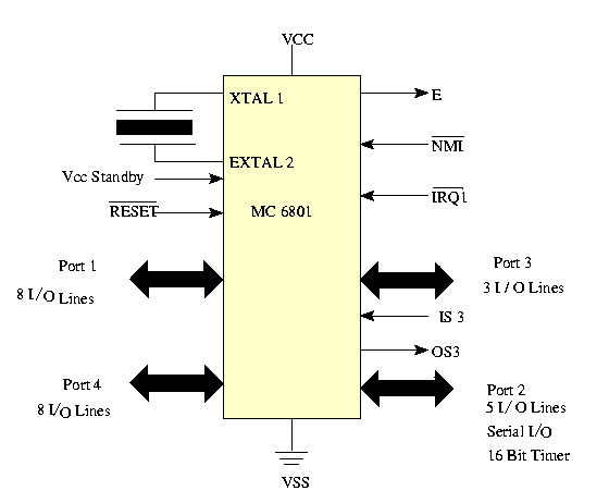
Fig - Single Chip Mode
To use in the expanded mode, it is given in the diagram given below:
Fig - MC6801 Microcomputer Family Block Diagram
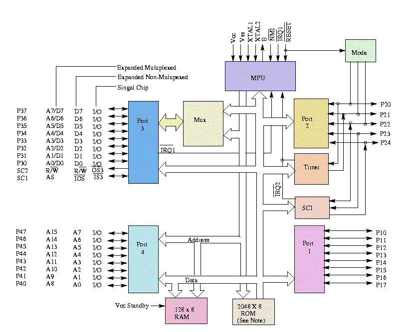
If used in the multiplexed mode, ports will be used as address lines. So you lose two ports and left with one port only. If you used the non-multiplexed mode, you loose something and port are used as address lines. This is the mode where you loose the flexibility of the ports.
Table
Common to all Modes :
|
Single Chip Mode 7
|
Expanded Non-Multiplexed Mode 5
|
| Expanded Multiplexed Modes 1, 2, 3, 6* Four memory space options (64K address space):
Port 3 is a multiplexed address/databus |
| Test Modes 0 and 4 Expanded Multiplexed Test Mode 0 May be used to test RAM and ROM Single Chip and Non-Multiplexed Test Mode 4 (1) May be changed to Mode 5 without going through Reset (2) May be used to test Ports 3 and 4 as I/O ports |
* The MC 6803 operated only in modes 2 and 3
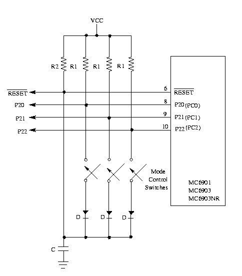
Fig - Typical mode programming circuits.
Different types of modes are:
In single chip mode, port 2 has two more signals - SC1 and SC2 and they are used for normal handshake transfer.
|
IS3 |
IS3 |
X |
OSS |
Latch |
X |
X |
X |
Port 3 Control & Status Register
| Latch Enable | Controls the input Latch of Port 3 when set, /IS3 negative edge latches the data. Cleared during reset. |
| OSS | Output strobe select. When clear strobe is generated by READ and when set strobe is generated by a write. Cleared on reset. |
| IS3 IRQE | Enables interrupt when IS3 flag is set. |
| IS3 Flag | Only Read flag. Set by |
SC1 functions as /IS3 and can be used to indicate that Port 2 input data is ready or output data has been accepted.
SC2 is configured as /OS3 and can be used to strobe output data or acknowledge input data.
SC1, SC2 in Single chip mode:
SC1 and SC2 is Expanded non-multiplexed mode:
SC1 is IOS input/output select. It can be used as CS for the external memory in the address range 0100-01FF.
SC2 is R/W
Expanded Multiplexed mode:
SC1 - Address Strobe (AS)
SC2 - R/W
In Multiplexed mode, full 16 bit address can be given where as in Non-multiplexed mode, external memory has register of 8 bits because only port 4 provides the address.
We will now take an application where Motorola 6801 can be used. (See figure below)
Figure - Block Diagram of Programmable Time
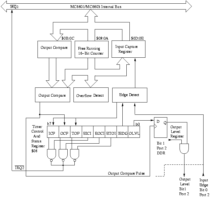
We have a free running counter, output compare register and input capture register.
| OLVL | Output level. OLVI is clocked to the output level register by a successful output compare |
| IEDG | = 0 Transfer on -ve edge
= 1 Transfer on +ve edge |
| ETDI | Enable timer overflow interrupt |
| EOCI | Enable output compare interrupt |
| EICI | Enable input capture interrupt |
| TOF | Timer overflow flag |
| OCF | Output compare flag |
| ICF | Input capture flag. Indicates proper level transition |