I bought this beautiful 1920x1200 monitor in 2006. I was very impressed with its image clarity and backlight uniformity. One day in January 2012, it gave a high-pitched whine when turned on. Within a few hours it was dead.
In India we run an import-use-discard sequence. Very few people understand how things work. Our technical education system is in shambles and an earlier culture of frugality and repair is now extinct. So in a vast majority of such cases, the monitor would be discarded, all five kilos of it, for what might be one small and inexpensive part.
Given my earlier experience with capacitor plague, I was encouraged to take a shot again. So I started by opening up the monitor. I promptly realized that Dell does not want the monitor to be opened up, but thanks to a very helpful video, I managed without damaging anything.
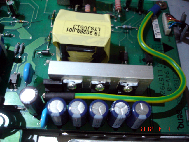
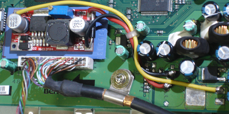
Generally, SMPS boards whine if they have dry caps, so I replaced the largest caps: the one after the 250VAC bridge, and the ones after the high-current diodes. The SMPS board provides two main voltage levels, 19V and 7V, to the display board. I checked that these voltage levels were fine. When the monitor remained dead after the cap change, I realized a 5A slow-blow fuse on the 19V line had blown. This was added evidence that the SMPS board may have overvoltaged its output, so, to be safe in future, I replaced the fuse and just after the fuse, bypassed the 19V DC to ground with a 27V 5W Zener diode and a 35V MOV. You can see the fat ground wire going to a lug securely bolted to the chassis. The caps are new low-ESR United Chemicons bought from Element14.
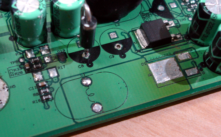
Moving to the display PCB, there were more signs of damage. A buck DC-DC converter (19V down to 5V) had broken: A P channel MOSFET Q1 had scorched the PCB around it, and Zener diode D19 had blown the track clear off. Also shown in the photo are the void spaces left behind after removing the two smoothing caps C8, C9, and the buck inductor L1. I have no idea if R3 and R17 were ever installed; probably not. Observe that in place of C8, I installed a 6.8V 5W Zener (topologically in the same place as D19) to protect the downstream load in case my experiments with the buck converter failed (as they did).
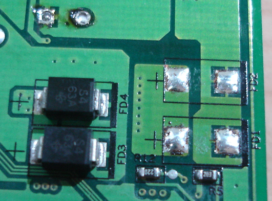
First I tried to replace the MOSFET (large square pad), but its gate controller was also kaput. The 6.8V Zener survived the few seconds it took me to measure some voltages; they were very abnormal. Without any help from Dell, it was impossible to debug further. So I decided to bypass the DC-DC converter entirely. After deciding this, I removed the flywheel Schottky diodes FD1 and FD2 soldered just below the MOSFET on the other side of the board. In principle, one should not need to remove these diodes, but 1. I wanted to remove all suspected parts and 2. the DC-DC converter has its own output protection circuit so I wanted to avoid any capacitor or diode in shunt that may affect its load regulation characteristics.
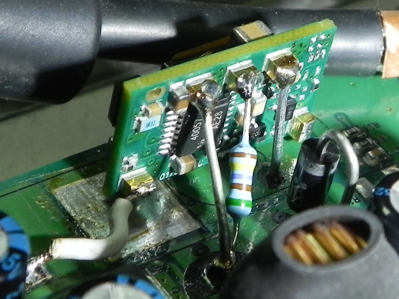
Using an old PC's SMPS, I supplied 5V to the PCB pad downstream from L1, and the monitor sprang back to life! So the next step was to look for a good quality POL buck DC-DC converter module. I chose the Murata OKI-T/3-W40P-C. It is only about 12x20mm, small enough to stand on its longer side on the display PCB. Also observe the stout lead inserted on the load side hole for L1.
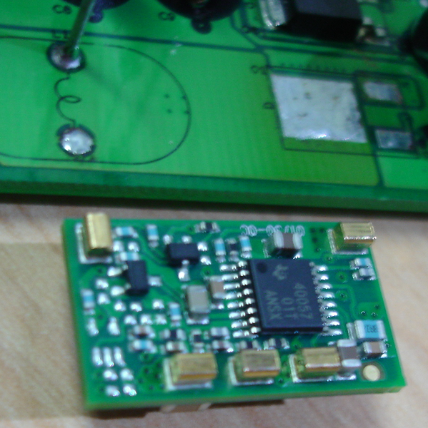
The tricky part was to solder four wires into gold pins in a 11x20mm PCB assembly held sideways. The stout tinned wires were cut off from 1N4001 diodes. The solder is not charred; it's mirror-like and reflecting black things. Observe that pins that go to through holes use stiff wire to hold the OKI-T/3-W40P-C in place, whereas the input wire (yellow) is a stranded soft wire, because it is soldered to a PCB pad without holes (used to be the MOSFET source pin). The voltage trimming resistor is 1.47kΩ 0.25W 0.5% 50PPM/C metal film.
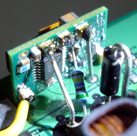
Note that the safety Zener stays put! The view from the other side, once all pins were soldered, is shown below.
As with the Tyan motherboard, I don't know how long this will last, but if I can take the monitor to the end of 2012, I am happy. I bought the monitor in 2006 for about 37,000 INR, and it cost me about 1,200 INR to repair it.
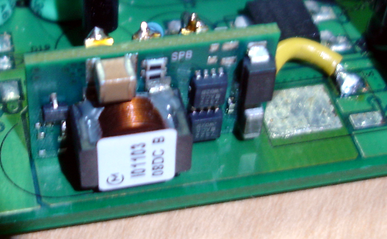
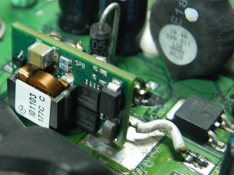
Update: Some months later, another Dell 2405FPW broke, with identical symptoms. This was an earlier release, with a bigger MOSFET Q1 that blew, and the Zener D19 was shorted as usual. (This time the track was spared but the Zener broke again during removal.) For this one I used a much cheaper (around 140 INR) DC-DC converter based on the LM2596S controller. This was a bigger assembly, so I needed to use two-sided sticky neoprene tape and an acrylic insulation sheet to mount it on a sparse area of the display PCB. You can see the obligatory 5W 6.3V Zener across the converter output in the photo below.
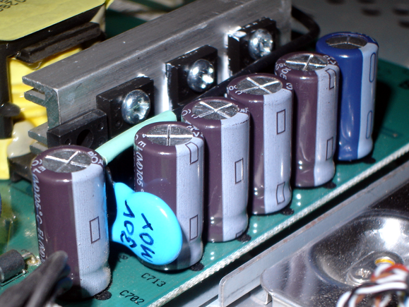
Here again I bypassed the 19V SMPS output after the (replaced) 5 amp slow blow fuse with a 30Vrms MOV and a 27V 5W Zener, in case the SMPS misbehaves. To mount the Zener I relocated the fuse to the bottom of the board, and used one of the holes freed up. The original location of the fuse in the deep valley between the tall caps and the power diode heatsink was very stupid. And the fuse leads were twisted on the soldering side, which made them difficult to remove. I cut the fuse open and pulled the leads out the other side. Speak of design for non-repair. In the first photo below you can see the Zener vertically mounted, with the MOV leads twisted around the axial Zener leads.
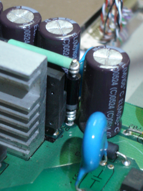
In the second photo below you see the MOV itself.
Update 2014/06/01: Another broken Dell, same fix.
Update 2017/07/15: The first Dell 2405FPW described in the beginning, bought in 2006, repaired in 2012, still works in 2017!